


Wind Tunnel Test Rig - Application: Fluid Mechanics Equipment
Price:
Get Latest Price
Minimum Order Quantity :
1 Piece
Brand Name :
Teknik
In Stock
Product Specifications
| Application | Fluid Mechanics Equipment |
| Product Type | WIND TUNNEL TEST RIG |
| Usage | Fluid Mechanics Equipment |
| Payment Terms | Cash Advance (CA), Cash in Advance (CID), Cheque, Telegraphic Transfer (T/T), Letter of Credit (L/C) |
| Packaging Details | Carton Box, Export Quality also Available |
| Main Export Market(s) | Asia, Middle East, Africa |
| Main Domestic Market | All India |
| Certifications | ISO 9001, 14001, CE |
Product Overview
Key Features
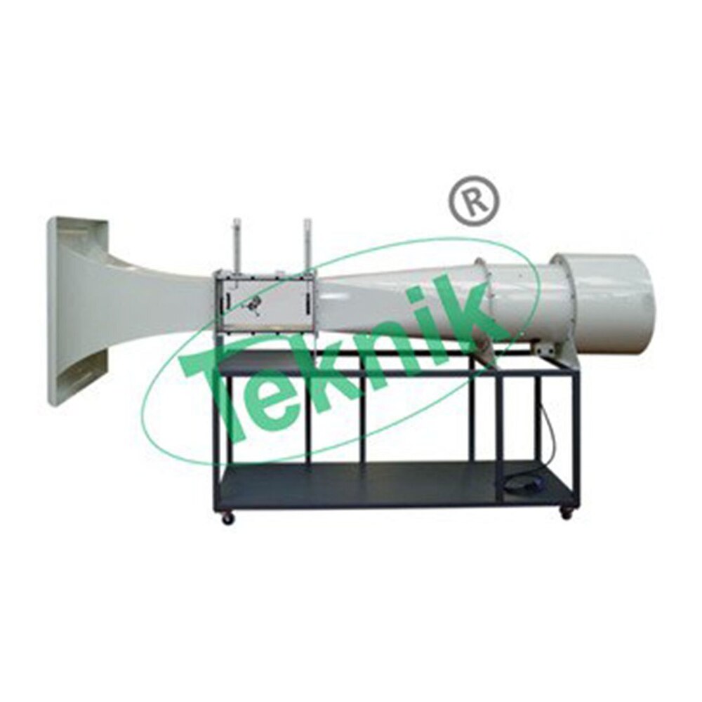
It is supplied as a complete self-contained facility mounted on castors for ease of movement.
Main equipment comprises the tunnel with a two-component balance system and an air speed indicator.
Air enters the test section through a carefully designed contraction followed by an aluminum honeycomb flow straightened designed to ensure that the flow is steady in both magnitude and direction and has a flat transverse velocity profile.
A low angle diffuser at the outlet end contributes to flow stability in the test section.
A five bladed fan is located at the outlet of the diffuser section.
The fan is driven by an AC motor supplied from an inverter speed control unit allowing smooth control of air speed.
The parallel octagonal test section is manufactured from clear acrylic and may be retracted on rails to permit unobstructed access to the models.
The two-component balance consists of a pair of balances supported on knife edges on mutually perpendicular axes parallel to and normal to the axial centre of the tunnel.
Lift and drag components of force exerted on the models under test are balanced by sliding weights along the arms of the balance until a state of null deflection is reached.
Graduations in units of force allow lift and drag to be read directly.
The complete assembly is linked to a simple oil filled damping pot.
Models are mounted on the balance within the working section and a protractor with cursor allows angles of incidence to be changed quickly and accurately while the tunnel is running.
The accuracy of the tunnel and its instrumentation make it suitable for undergraduate and simple research work.
Features:-
Contraction and diffuser: precision glass fiber moldings
Test section: clear acrylic, which retracts to permit access to the models.
Adjustment of models can be made with the tunnel in operation.
Fan: Variable-speed motor driven unit downstream of the working section permitting steeples control of airspeed between 0 and 26ms-1
Balance: Lift and drag
Lift 7.0N, Drag 2.SN, Sensitivity 0.01 N
Air speed: Indicated on inclined manometer directly calibrated in m/s
Support structure: A strong steel frame including working surface and fitted with castors for easy movement
Demonstration and Measurement Capabilities:-
A selection using the models and instrumentation provided are:-
Investigation of the development of the boundary layer on a flat plate by measurement of the total head distribution
Flow visualization studies around an aerofoil
Measurement of pressure distribution around an aerofoil at various angles of attack
Measurement of pressure distribution around a cylinder
Measurement of lift and drag on an aerofoil with leading edge slot and trailing edge flap
Velocity and pressure distribution measurements using a Pitot static tube and yaw probe
Measurement of drag for a selection of models of different shapes but common equatorial diameter
Demonstration of flutter of an aerofoil
Calibration of the wind tunnel velocity indicator using a Pitot static tube and inclined manometer
Investigation of the wake behind a cylinder or aerofoil using a wake survey rake
Technical Specifications:-
Suitable for undergraduate and simple research work.
Working section: 304mm wide x 304mm high x 457mm long (octagonal cross- section)
Contraction area ratio: 3:1
Motor rating: 1.SkW
Flow visualization studies around an aerofoil and cylinder
Measurement of pressure distribution around an aerofoil at various angles of attack or around a cylinder
Measurement of lift and drag on an aerofoil with leading edge slot and trailing edge flap
Velocity and pressure distribution measurements using a pitot static tube and yaw probe
Measurement of drag for models of different shapes but common equatorial diameter
Demonstration of flutter of an aerofoil
Calibration of the wind tunnel velocity indicator using a pitot static tube
Investigation of the wake behind a cylinder or aerofoil using a wake survey rake
Company Details
Focusing on a customer-centric approach, MICRO TEKNIK has a pan-India presence and caters to a huge consumer base throughout the country. Buy Scientific Instruments in bulk from MICRO TEKNIK at Trade India quality-assured products.
Business Type
Exporter, Manufacturer, Distributor, Supplier, Trading Company
Employee Count
25
Establishment
1973
Working Days
To
GST NO
06ACMPJ7244B1ZS
Certification
ISO 9001 : 2015
Related Products
Pressure Testing Equipment - MS Material, 440 Volt Electric Power Supply | Industrial Application, Blue Color, Robust Usage
Price: 580000.00 INR
MOQ - 1 Piece/Pieces
Anish Hydraulics Pvt. Ltd.
Pune, Maharashtra
Flushing And Pressure Test Rig - Steel 1500x1000x1200 mm Red, 1000 Bar Pressure, 50 LPM Flow, Reliable Operation
Stephen Balaram Engineering Private Limited
Ahmedabad, Gujarat

Filter Hydrostatic Burst Pressure Test Rig Equipment - Color: Silver
Price: 10000.0 INR
MOQ - 1 Unit/Units
Filtration Engineering & Consultants
New Delhi, Delhi

Control Pressure Test Rig Machine
Price: 85000 INR
MOQ - 1 Piece/Pieces
Hiteam Fluid Control System
Coimbatore, Tamil Nadu
Grey High Pressure Test Rig
Price: 50000-350000000 INR
MOQ - 1 Unit/Units
Primicon Technologies Llp
Pune, Maharashtra
Explore Related Categories


More Products From This Seller


Seller Details
GST - 06ACMPJ7244B1ZS
Ambala Cantt, Haryana
CEO
Mr Vikas
Members since
14 Years
Address
Plot No. 73, Vikaspuri, Industrial Area, Ambala Cantt, Haryana, 133001, India
pressure test rigs in Ambala Cantt
Report incorrect details


