Tank Type Ac Resonant Test System
Price:
Get Latest Price
In Stock
Product Specifications
| Type | Resonant Tester |
| Color | Red |
| Voltage | High Voltage |
| Frequency | Variable |
| Usage | XLPE power cable testing and routine testing |
| Cooling | Oil-cooled |
| Standards | IEC |
| Features | High capacitance, XLPE cable test, Variable frequency, Compact design, Efficient testing |
Product Overview
Key Features
Tank Type AC Resonant Test System
Introduction
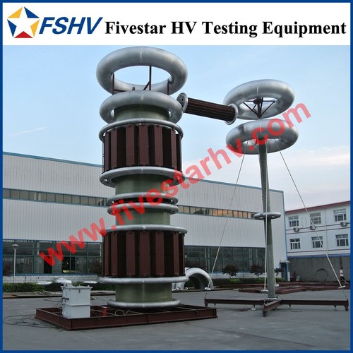
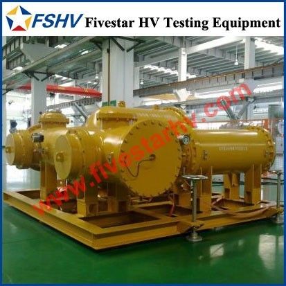
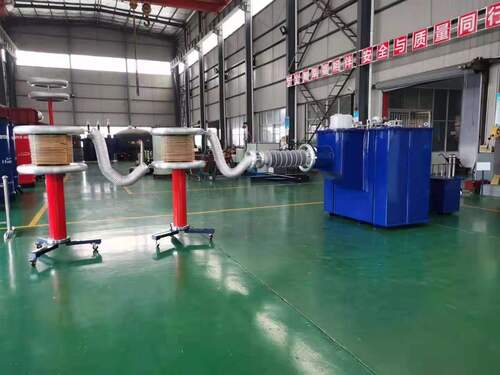
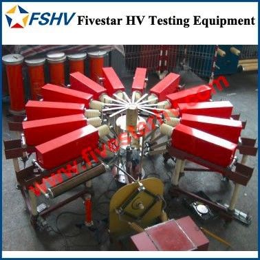
TRST series tank type AC resonant test systems are designed for high capacitance load, special for XLPE power cables. There are variable frequency type (mainly used for XLPE cables field test) and variable inductance type (mainly for factory routine test).
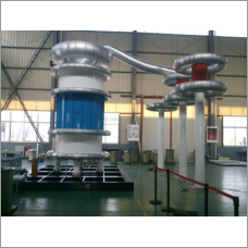
TRST series tank type reactors are situated in an enclosed and earthed metal tank and filled with transformer insulation oil inside, additional voltage taps are possible, the output voltage is fed out through the tap-changers by HV bushings. These reactors extend application range, and satisfy testing for cables of various voltage classes.
Application
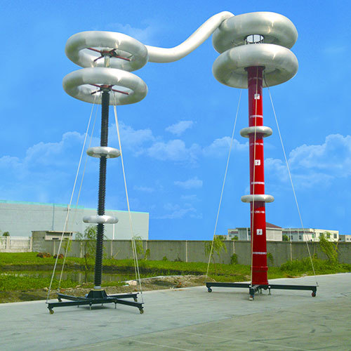
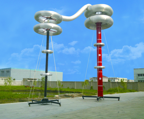
AC resonant test systems are mainly used to output AC voltage for high voltage routine, type and development testing of capacitive test objects. These systems exert the principle of series resonance, as per f=1/2LC, the connection of HV reactors (inductance L) to a capacitive loads (capacitance C) form an oscillating circuit with the frequency (f) of power supply.
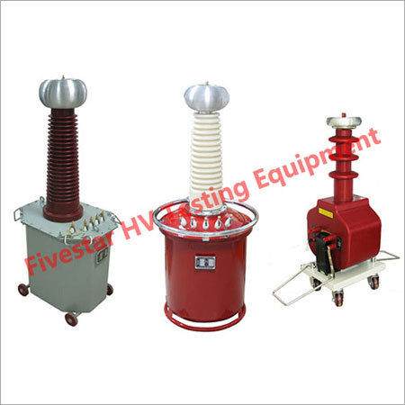
Compared to conventional AC test transformers, the relatively lower power required (1/Q), smaller dimension and lighter weight favor these systems as the most practical for field testing, and large capacitance loads.
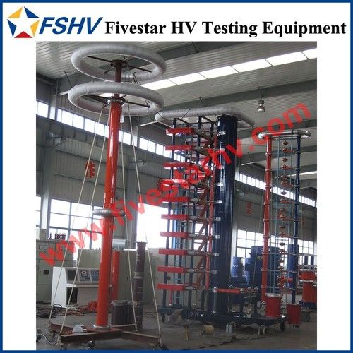
Configuration
Essential
Regulating transformer
Exciter transformer
HV reactor
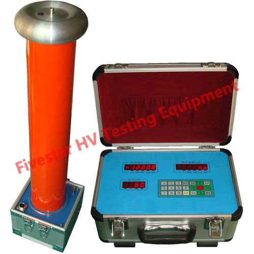
Capacitor divider
Optional
Switchgear cabinet
Compensation reactor
Power line filter
HV filter
Principle
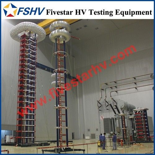
Series resonant circuit consists essentially of an inductor in series with a capacitive test object or load connected to a medium-voltage power source. Alternatively it may consist of a capacitor in series with an inductive test object. By varying the circuit parameters or the supply frequency, the circuit can be tuned to resonance, when a voltage considerably greater than that of the source and of substantially sinusoidal shape is applied to test object.
The stability of the resonance conditions and of the test voltage depends on the stability of the supply frequency and of the test system characteristic, described by the quality factor, which is the ratio between test reactive power and power loss.
When a discharge occurs, the circuit capacitance discharges instantaneously and then follow-through current from the source is relatively low. The limit follow-through current generally results in less damage to the test object.
Company Details
Focusing on a customer-centric approach, FIVESTAR HV TESTING EQUIPMENT CO LTD. has a pan-India presence and caters to a huge consumer base throughout the country. Get Testing & Measuring Equipment from FIVESTAR HV TESTING EQUIPMENT CO LTD. at Trade India quality-assured services.
Business Type
Exporter, Manufacturer, Service Provider, Supplier
Employee Count
310
Establishment
1970
Working Days
Monday To Sunday
Related Products
Variable Frequency AC Resonant Test Systems
Jiangsu Jinxiu High Voltage Electric Co.,ltd.
Yangzhou, Jiangsu
Ac Resonant Test Systems With Module Type
Price: 5800-7920 USD ($)
MOQ - 1 Set/Sets
San Men Xian Shi Xuan Electric Co., Ltd.
Yangzhou, Jiangsu


AC Resonant Test System - High Voltage 50/60 Hz Indoor/Outdoor Use | Advanced Resonant Technology for Reliable Testing
Power Electric Co., Ltd
Yangzhou, Jiangsu
Blue Ac Resonant Test System With High Voltage Capacity
San Men Xian Shi Xuan Electric Co., Ltd.
Yangzhou, Jiangsu
AC Resonant Test Systems - High Voltage, Expandable Modules | Versatile Testing for Cables, Transformers, Bushings, Generators & Capacitors
Jiangsu Jinxiu High Voltage Electric Co.,ltd.
Yangzhou, Jiangsu

AC Resonant Test Systems With Variable Inductance
Shanghai Jiu Zhi Electric Co., Ltd.
Yangzhou, Jiangsu
Explore Related Categories


More Product From This seller


Seller Details
Yangzhou, Jiangsu
Sales Manager
Mr. Roger Chen
Address
Xiancheng Industrial Park, Jiangdu District, Yangzhou, Jiangsu, 225200, China
ac resonant test system in Yangzhou
Report incorrect details