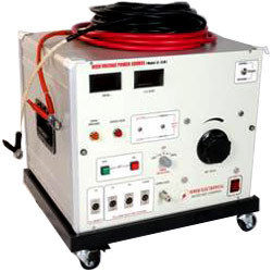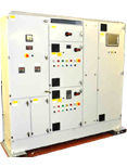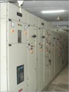
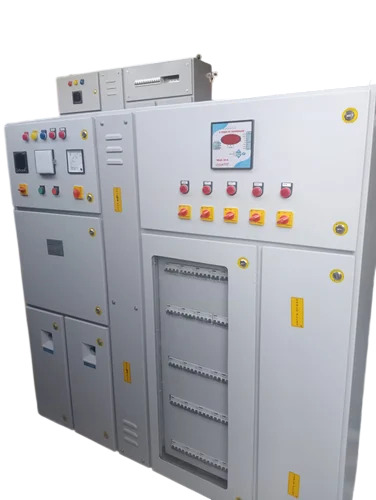
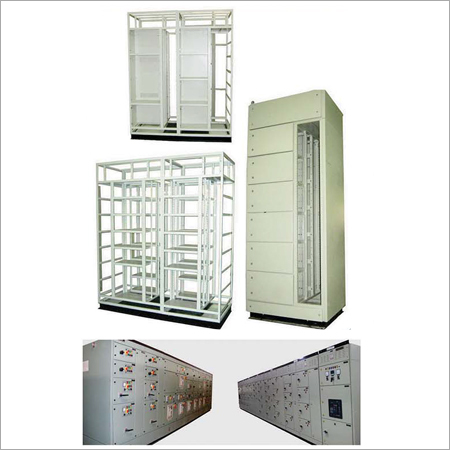
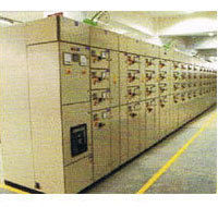
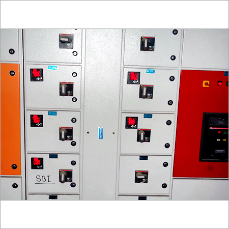
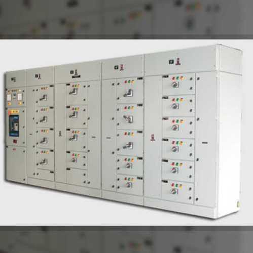
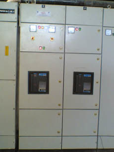
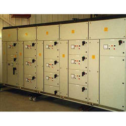
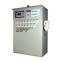
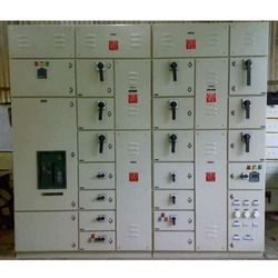
Multi Power Control Centre / Motor Control Centre
Price:
Get Latest Price
In Stock
Product Specifications
| Enclosure | Cubicle Type |
| Features | Reliable Power, Safe Operation, Modular Design, Easy Installation, Customizable, Durable Build, Efficient Control |
| Frequency | 50Hz |
| Material | CRCA Steel |
| Mounting | Floor/Wall |
| Standards | IEC, BS |
| Usage | Motor & Power control |
| Voltage | 415V, 3-phase |
Product Overview
Key Features
SALIENT FEATURE 1. ELECTRICAL SUPPLY CHARACTERISTICS Normal Voltage : 415 Volts, 3 Phase, 4 Wire, 50 Hz, AC : Voltage Plus/Minus 6% Frequency - Plus/minus 3% combined - Plus/Minus 6% 2. STANDARDS All materials, equipment and accessories used in the manufacture shall confirm to relevant Indian/British/IEC 3. CONSTRUCTIONS a) 14/16 SWG. CRCA sheet steel cubicle type Indoor/Outdoor floor mounting free standing / wall mounting. b) Totally enclosed dust damp and vermin proof. c) Non deteriorating synthetics rubber gasket shall be used between all adjacent units and beneath all covers and door. d) Vents and other opening shall be provided with non-rusting screens for vermin proofing. e) MCC/PCC shall be same height, width and depth as well as bolted together to form a continuous flush switch board, suitable for front board, suitable for front board, operation. f) The MCC/PCC shall be fabricated from structural steel section and sheet steel. The base channel shall be of 3mm thick and 75mm wide body sheet steel shall have 1.5/2 mm thickness. The design and construction shall be rigid and robust, welded construction will be provided. All steel works shall be flawless and have smooth finish. g) Adequate lifting facilities shall be provided on each section of MCC lifting eyes may be removable/foldable. h) Inside surface shall be painted with anti-condensation paint. All feeder compartment shall be provided with doors, doors shall be hinged type with quick release fasteners and lift off type hing. Doors opening shall be restricted, by suitable means to avoid damage to door mounted equipment. i) Separate compartments shall be provided for MCC incoming and outgoing feeders, bus bar , cable boxes, which will be fully and effectively segregated from one other, so that fault in any one compartment shall not cause damage to equipment in any other compartment. j) ISOLATOR COMPARTMENT Isolator to be interlocked with door to prevent opening or closing of the door in the closed (ON) position of the Isolator , in case of compartment type of feeders, provision for padlocking the isolator in open position also could be made on request. k) BUS BAR COMPARTMENT TPN Bus bar of the rating as specified shall be provided in separated compartment, such compartment in each panel shall have front removal cover properly fixed with suitable number of screws. l) CABLE BOX COMPARTMENT The outgoing feeders shall be wired upto terminal box, with shall be mounted in separate compartment at top. All covers to this compartment shall also be removable type. Considering size and number of cables to be connected bus bars shall provided in cable box. 4. EQUIPMENT/COMPONENTS: A) BUS BARS 1) Bus bar shall be of uniform cross section of electrolytic quality aluminum rated as per current rating .Busbar shall be air insulated, enclosed, having barriers /covers. Caution live busbars name plate shall be on barriers/covers. B) FEEDER ARRANGEMENTS 1) Each feeder shall be provided with barriers on all sides such that compartmentalization is possible. 2) Compartment size shall be integral multiples of one or two basic size. 3) The control components except those coming on doors shall be mounted on a common base plate ,fixed with the frame of the vertical section. 4) Each feeder designation as per single line diagram .The labels shall be black of Perspex acrylic unbreakable sheets with 20mm size letters engraved in white. C) ISOLATOR 1) Isolators shall be two position (ON/OFF) type, heavy duty ,load break ,quick make and quick break type and suitable for front of board operation. 2) Isolator for motor feeders shall be motor duty type i.e. capable to interrupting the locked rotor current of motors. 3) All live terminals on the isolators to be adequately/shrouded to prevent accidental contact and danger to the personnel. D) WIRINGS 1) All control wiring shall be carried out through common wire ways. These shall not cross the bus bar chamber. All control wiring shall be easily accessible for maintenance. 2) Power wiring shall be carried out with PVS insulated standard copper/ Aluminum Conductors of 650 V grade having adequate current carrying capacity. 3) Necessary colour codes shall be adopted for power and control wiring for easy identification. 4) Control wiring shall be single core/ multicore ,PVC insulated copper conductor of size 2.5 mm cross section and with 650V grade flame resisting insulation. 5) Circuit involving current transformers shall have 1100V grade cable. 6) Each control wire shall be identified at both ends with wire designations by means of unbreakable ferrules, in accordance with IS:375. 7) Control wiring where ever terminated shall be in single layer, formation. Double layer wiring shall not be adopted ,not more than two wires shall be connected to one terminal. 8) Connection from vertical bus bars to the feeders switches shall withstand short circuit level specified, in case fuses are provided on the incomer, these connections shall be designed to safety withstand the cut-off current of the above fuses. E) EARTHING 1) An aluminum earth bus of 40x5mm size be run the length of the MCC. All non- current carrying metal work of the switch board shall be effectively bonded to this earth bus. 5. NAME PLATES & LABELS A) Name plates giving designation of each MCC Panel shall be fixed prominently on the top of the panels. B) Name plates shall also be provided below the individual components mounted on the front of the panels, such as indicating lamps, metering etc. to indicate the device functions. C) Name Plates shall be rear engraved perspex with white letters on black back ground. All name plates shall be clamped on the panel with counter such type self tapping screws to permit interchangeability , when required. 6. PAINTING & FINISHING The colour of paint shall be light grey as per IS631 shade or Siemens Grey shade. 7. STOVE ENAMEL PAINTING In this process after the surface cleaning de-greasing and de-oiling using Acids etc. the surface is rinsed and washed with water and than surface is applied with red oxide, after the red oxide treatment the surface is washed with water thoroughly and than putty is applied on rough/uneven surface. After than two coat of paints are applied. After the painting the switchboard is shifted to a backing oven at 180C for curing. 8. POWER COATING PAINTING After the surface treatment panel is shifted to Powder Chamber, where powder is spared and after powder coating , board is shifted to backing oven for curing. After curing it is removed to assembling section. 9. CPRI TESTED Our panels PCC`s and MCC`s are CPRI tested for Short Circuit and Temperature rise up to 4000 Amps. Rating upto 65KA.. 10. IP-55 Our Junction boxes are IP-55 testing from ERDA ,Vadodara . 11. ISO-19002 We are the process of adopting Quality system at our works for which quality systems are being followed. All the instruments are being calibrated every year.Test report and installation manual are being Provided with the products. All drawings are made with the help of the installed AutoCad program in our computers
Company Details
Business Type
Manufacturer, Service Provider, Supplier, Trading Company
Employee Count
100
Establishment
2000
Working Days
To
GST NO
08AABCD2168G1ZT
Payment Mode
Online Payments (NEFT/RTGS/IMPS)
Related Products

Motor Control Center Panel - High Grade Raw Materials, Durable Three Phase Design | Meticulously Supervised Manufacturing Process
Power Control Electricals
Udaipur, Rajasthan

Motor Control Center Panels - High-Performance Design, Premium Raw Material Compliance, Customized Specifications
Divya Electricals
Jaipur, Rajasthan


Motor Control Centers - High-Quality Centralized Motor Control | Remote Control Panels, Control Desk Integration
Western Control & Automation
Jaipur, Rajasthan
Motor Control Center Panels - Enclosed Sections with Common Power Bus, Includes Variable Frequency Drives and Programmable Controllers
Singhvi Technocrate Private Limited
Udaipur, Rajasthan

Motor Control Centers - 1600 A Operational Current, 50 kA Short Circuit Withstand Capacity, IP 52 Protection
A.c. Power Control & Switch Gears
Bhiwadi, Rajasthan

Motor Control Centers - High-Quality Fabrication with Superior Durability | Exceptional Performance and Reliability
Sankhla Group
Neemrana, Rajasthan
Explore Related Categories


More Products From This Seller


Seller Details

GST - 08AABCD2168G1ZT
 Rating
Bhilwara, Rajasthan
Director
Mr Sanjeev Kumar Lodha
Address
B No. G-68, RIICO Industrial Area, Biliya, Bhilwara, Rajasthan, 311001, India
motor control center in Bhilwara
Report incorrect details