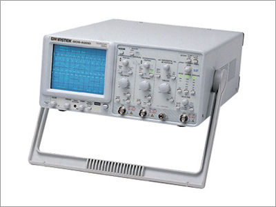

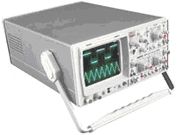
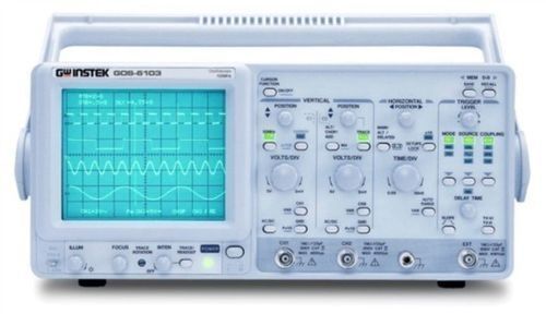
Durable 200mhz Bandwidth, 2 Channel Analog Oscilloscope
Price:
Get Latest Price
In Stock
Product Specifications
| CRT Type | 6-inch rectangular |
| Bandwidth | DC~200MHz |
| Rise Time | 1.75ns |
| Input Impedance | 1MΩ |
| Vertical Sensitivity | 2mV~5V/div |
| Sweep Time | 20ns~0.5s/div |
| Trigger Sensitivity | 50mV~1.5V |
| Features | 200MHz Bandwidth, Dual Channel, Delayed Sweep, Auto Set, Built-in Counter, Cursor Readout, Memory Settings, Easy Operation |
Product Overview
Key Features
The GOS-6200 Analog Oscilloscope satisfies the massive needs in diverse
professional applications up to 200MHz. Embedded with Delay Sweep and
Hold Off features, the GOS-6200 is capable of measuring sophisticated
signals. The Cursor Readout with 7 measurements, Panel Setup
Save/Recall, and the built-in 6 Digit Universal Counter all makes
waveform observation and measurement easier, faster and more accurate.
The advanced Time Base Auto Range function, acquires waveforms with the
push of a button convenience. The Counter function, 10 memory settings
and advanced Auto functions are among some of the extra benefits
available in GOS-6200.
FEATURE
- S200MHz Bandwidth, Dual Channel, Delayed Sweep
- Auto Set
- Built-in 6 Digits Counter
- Cursor Readout with 7 Measurements
- 10 Sets Memory for Front Panel Setting Save & Recall
- TV-Line Selection (NTSC, PAL, SECAM)
- Panel Setup Lock of Digital-Control Functions
- Buzzer Alarm
- LED Indicators
- Trigger Signal Output
- Z-axis Modulation Input
- SMD Technology, High Stability and Reliability
SPECIFICATIONS
CRT | |||||||||
Type | 6-inch rectangular type with internal graticule; | ||||||||
Accelerating Potential | 14 kV approx. | ||||||||
Illumination | Continuously adjustable | ||||||||
Z-axis input | Coupling : DC | ||||||||
VERTICAL SYSTEM | |||||||||
Sensitivity | 2mV~5V/div, 11 step in 1-2-5 sequence | ||||||||
Sensitivity Accuracy | 3% (5div at the center of display) | ||||||||
Vernier Vertical Sensitivity | Continuously variable to 1/2.5 or less of panel-indicated value | ||||||||
Bandwidth(-3dB) | DC~200MHz (5mV/div:DC~150MHz) ; (2mV/div:DC~20MHz) | ||||||||
Rise Time | 1.75ns (5mV/div:2.33ns, 2mV/div:17.5ns) | ||||||||
Signal Delay | Leading edge can be monitored | ||||||||
Max. Input Voltage | 400V(DC+AC peak) at 1kHz or less | ||||||||
Input Coupling | AC, DC, GND | ||||||||
Input Impedance | 1M 2% // approx. 25pF | ||||||||
Vertical Mode | CH1,CH2,DUAL(CHOP/ALT), ADD, CH2 INV. | ||||||||
Bandwidth Limited | 20MHz | ||||||||
Common-Mode Rejection Ratio | 50:1 or better at 50kHz | ||||||||
Dynamic Range | 8 div at 100MHz; 5div at 200MHz | ||||||||
HORIZONTAL SYSTEM | |||||||||
Horizontal Modes | MAIN(A), ALT, DELAY(B) | ||||||||
A(main) Sweep Time | 20ns~0.5s/div, continuously variable (UNCAL) | ||||||||
B(delay) Sweep Time | 20ns~50ms/div | ||||||||
Accuracy | 3% ( 5% at x 10 MAG) | ||||||||
Sweep Magnification | x 10 (maximum sweep time 2ns/div) | ||||||||
Hold Off Time | Variable | ||||||||
Delay Time | 1s~5s | ||||||||
Delay Jitter | Better than 1:20000 | ||||||||
Alternate Separation | Variable | ||||||||
TRIGGER | |||||||||
Trigger Modes | AUTO, NORM,TV | ||||||||
Trigger Source | CH1, CH2, LINE, EXT, EXT/10 | ||||||||
Trigger Coupling | AC, DC, HFR, LFR, NR | ||||||||
Trigger Slope | "+" or "-" polarity or TVsync polarity | ||||||||
Trigger Sensitivity | Mode | Frequency | INT | EXT | EXT/10 | ||||
AUTO | 10Hz~20MHz | 0.35div | 50mV | 500mV | |||||
NORM | DC~20MHz | 0.35div | 50mV | 500mV | |||||
TV | sync signal | 1div | 200mVpp | 2Vpp | |||||
Trigger Level Range | INT: 4div or more; EXT: 0.4V or more; EXT/10: | ||||||||
TV Triggering | Mode:TV-V, TV-H, TV-LINE | ||||||||
TV-Line Selection | Standard | Field 1 | Field 2 | ||||||
NTSC (525H) | 1H ~ 263H | 1H ~ 262H | |||||||
| 1H ~ 313H | 1H ~ 312H | |||||||
Max. External Input Voltage | 400V(DC+AC peak) at 1kHz | ||||||||
External Input Impedance | 1M5% // approx.25pF | ||||||||
X-Y OPERATION | |||||||||
Mode | X-axis: selectable CH1, EXT, EXT/10 | ||||||||
Sensitivity Accuracy | 2mV~5V/div3% | ||||||||
X-axis Bandwidth | DC~500kHz(-3dB) | ||||||||
Phase Error | 3 or less from DC~50kHz | ||||||||
OUTPUT SIGNAL | |||||||||
Trigger Signal Output | Voltage: approx. 25mV/div into 50 | ||||||||
Calibrator Output | 1kHz Square wave, 2Vpp2% | ||||||||
CURSOR READOUT FUNCTION | |||||||||
Cursor Measurement Function | V, V%, VdB, T, 1/ T, T%, | ||||||||
Cursor Resolution | 1/100 DIV | ||||||||
Effective Cursor Range | Vertical: 3div ; Horizontal: 4 div | ||||||||
Panel Setting Display | Vertical: V/div(CH1,CH2),UNCAL,ALT/CHOP/ADD,INV, probe | ||||||||
AUTO MEASUREMENT FUNCTION | |||||||||
Parameter Function | FREQ, PERIOD,WIDTH,DUTY (+ or - polarity | ||||||||
Display Digits | Max. 6-digits, decimal | ||||||||
Frequency Range | 50Hz ~ 200MHz | ||||||||
Accuracy | 1kHz ~ 200MHz : 0.01% ; 50Hz ~ 1kHz : 0.05% | ||||||||
Measuring Sensitivity | > 2 div (Measuring source selected from CH1 and Ch2 as | ||||||||
SPECIAL FUNCTION | |||||||||
Auto Set | Input Channel : CH1, CH2 | ||||||||
Panel Setting Save & Recall | 10 sets | ||||||||
Panel Setups Lock | Provided | ||||||||
POWER SOURCE | |||||||||
AC 100V/120V/230V10% , 50/60Hz | |||||||||
ACCESSORIES | |||||||||
User manual x 1 | |||||||||
DIMENSIONS & WEIGHT | |||||||||
310(W) x 150(H) x 470(D) mm | |||||||||
Company Details
Focusing on a customer-centric approach, BETA ENGINEERS has a pan-India presence and caters to a huge consumer base throughout the country. Get Electrical Testing & Measuring Equipment from BETA ENGINEERS at Trade India quality-assured services.
Business Type
Importer, Manufacturer, Service Provider, Supplier
Employee Count
25
Establishment
1988
Working Days
Monday To Sunday
GST NO
27AASPB3600P3ZF
Related Products
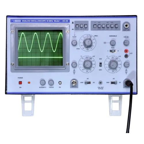
Analog Oscilloscope - 30 MHz Bandwidth, Dual Channel with 20ns Time Base | X10 Magnification, Active TV Sync Separator, Variable Hold-Off
Skyking Instruments
Mumbai, Maharashtra


Analog Oscilloscope - High-Grade Electronic Materials | High Strength, Durable, Accurate Measurement
Sai Harsh Enterprises
Badlapur, Maharashtra
Analog Oscilloscope (Cro) - 100 MHz Dual Channel, DC Sensitivity 2mV/DIV-5V/DIV, 6 Graticule Options | Memory Recall, Buzzer Alarm, Z-Axis Modulation
MOQ - 10 Piece/Pieces
Micro Teknik
Ambala Cantt, Haryana
Analog Oscilloscope - 30MHz/60MHz Bandwidth, 6" CRT Dual Channel Display | Dual Trace, X-Y Mode, Sensitivity Up to 1mV/Division
Expert Labo
Ambala Cantt, Haryana
Analog Oscilloscope 30 Mhz - Color: White
Price: 22500.0 INR
MOQ - 1 Unit/Units
Mannu Enterprises
Delhi, Delhi

Analog Oscilloscope - 10MHz to 100MHz Frequency Range | Precise Waveform Observation for Accurate Test Measurements
Vamara Techware
Coimbatore, Tamil Nadu
Analog Oscilloscope - Precision Engineered Design | Aesthetic, Durable, Rigidly Tested for Flawless Performance
Lab Electronics
Chennai, Tamil Nadu
Explore Related Categories


More Product From This seller


Seller Details
GST - 27AASPB3600P3ZF
Pune, Maharashtra
Proprietor
Ms. Alka R. Birje
Address
9, Chitra Apartments, 966/A , Off. Vetal Maharaj Chowk, Gokhalenagar Road, Shivajinagar, Pune, Maharashtra, 411016, India
analog oscilloscope in Pune
Report incorrect details