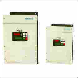
In this industry, we are counted amongst the most eminent manufacturers and suppliers of Inverter AC Drives. These drives are made by our professionals using supreme quality raw materials and advanced methodologies. Our offered drives are widely preferred by our patrons due to their features like multi-step speed control system for trouble-free automation, easy diagnosing with fault history record and low motor operational noise with excellent switching frequency. Inverter AC Drives are provided digital & multi parameter system for different controlling applications.SALIENT FEATURES Space Vector Modulation with bus ripple compensation for reduced motor vibration Advanced switching patterns for smooth rotation of Motor at low speeds Optimum utilization of input voltage for improved form factor Electronic Thermal Overload for Motor protection Advanced algorithm for smooth speed variation Slip compensation for better speed regulation Selection Chart Parameter/Model IND2 K2 IND 3 K 7 IND 5 K 5 IND7K5 IND11K IND15K IND18K IND22K Applicable Motor output (kW) 0.4~2.2 3.7 5.5 7.5 11.0 15.0 18.5 22.0 Inverter output at 415V (kVA) 4.3 7.2 10.8 14.4 18.0 21.6 28.0 32.3 Rated output current (Amps.) 6.0 10.0 15.0 20.0 25.0 30.0 40.0 45.0 Nett Weight (Kg) 9.0 13.0 13.0 13.0 18.0 18.0 19.0 19.0 Dimensions (HxWxD in mm) 364 x 218 x 20 1 400 x 240 x 229 480 x 278 x 236 480 x 278 x 266 Technical Specification Input Rating Power supply 3 Phase, 380V / 415V, 50 / 60 Hz Allowable variations Voltage: +10%, -15%, Frequency : +/-5%, imbalance less than 3% Output voltage 3 phase, 380V to 440V (same as input voltage) Output Rating Output frequency 1 to 128Hz Frequency stability Digital setting : +/- 0.01% of Max. frequency (-10 C to +50 c) Analog setting : +/- 0.2% of Max. frequency (at 25 C +/- 10C) Overload capacity 150% for one minute Control system Space vector modulation with bus ripple compensation Control Specification Frequency control range 1 to 128Hz Adjustable current limit 30 to 200 % of rated current Maximum frequency 1 to 128Hz Base frequency 40 / 50Hz Carrier frequency 5.3Hz fixed Frequency setting Up /Down keys, potentiometer 1 kohm (0.5 W),Raise / Lower switch, Analog input : 0 to 10V, 0 to -10V, 4 to -20mA, +10V to -10V (polarity based speed reversal), 8 preset frequencies with x1, x2 & x3 terminals Frequency resolution Digital : 0.01Hz step (at Fmax. 50Hz)Analog : 0.05Hz step (at Fmax. 50Hz) Jump frequency control 3 points with adjustable jump range Accel / Decel. rate 0.1 to 128Hz per second (4 independently adjustable Accel. & Decel.) Braking torque Dynamic braking (20 to 150%) Slip compensation Available (Load current dependent) Max./Min. frequency Frequency lower limit / Frequency upper limit (Fstart to Fmax.) Fault history display Present fault and upto 19 previous faults Starting frequency 1 to 10Hz Inverter trip and error messages Under voltage, Over voltage, Inverter Overload, Short circuit, CMOS error, Over current during acceleration / deceleration / steady state conditions, THR fault, Heat sink overheating & Electronic thermal overload trip. Protection Functions Stall prevention, Auto restart during instantaneous power failure for 15ms duration Analog output Frequency / Motor Current Indication and Control External output 2Nos. Programmable open collector outputs, 1No. Fault alarm relay output and 1 no. Programmable relay output. Display unit 4 Seven segment LED: Output frequency, RPM Load current & DC bus voltage 16 x 2 Character LCD with back-lit and 6 Keys touch pad for programming Installation Location Indoor not more than 1000 Mts. Above sea level. Do no install in a dirty location or expose to corrosive gases or direct sun rays. Environmental Conditions Ambient temperature 10 C to +40 C (-10 C to +50 C when mounted inside the switch board) Humidity 90 % RH or less (non-condensing) Cooling system Forced air cooling type Optional RS 232C / RS 485 (serial Communication), Dynamic braking facility & / or Resistor unit, input AC Reactor